PCB Design
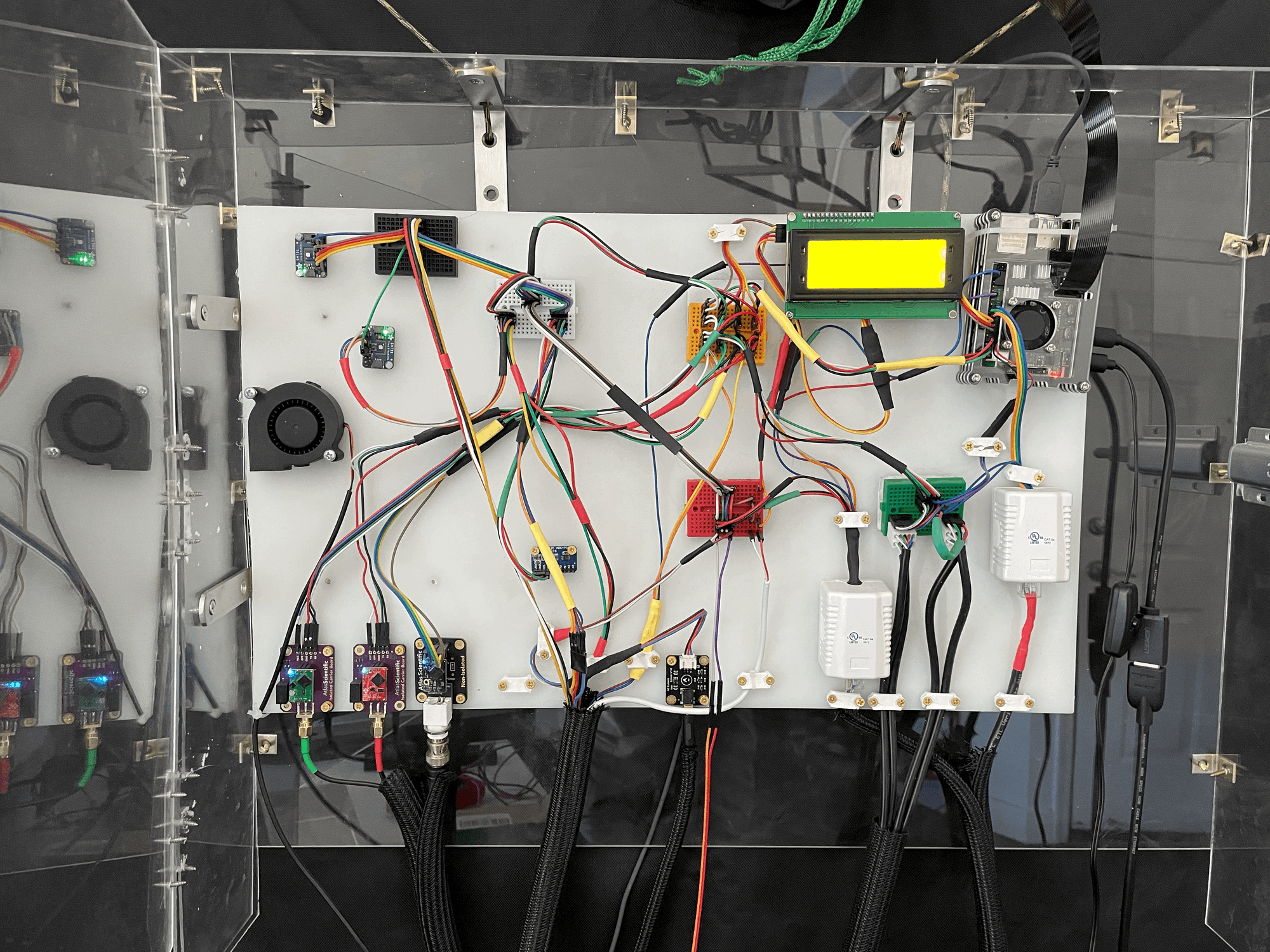
After having completed the wiring of the sensors using jumper cables it became an obvious source of improvement. The jumper cables had done their job at verifying the sensors worked but were less reliable than what a printed circuit board would provide.
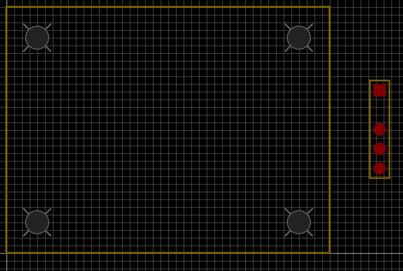
I had recently started working for a microelectronics company and had become much more familiar with PCB design and electronics in general so I felt confident this would something I could accomplish. After some research I decided EASYEDA was going to be the best software to go with. They had a well documented tutorial and it seemed to have the lowest barrier to entry. In the program you will first create a sensor. This sensor contains two parts, the pin connections and a footprint (size of the part)
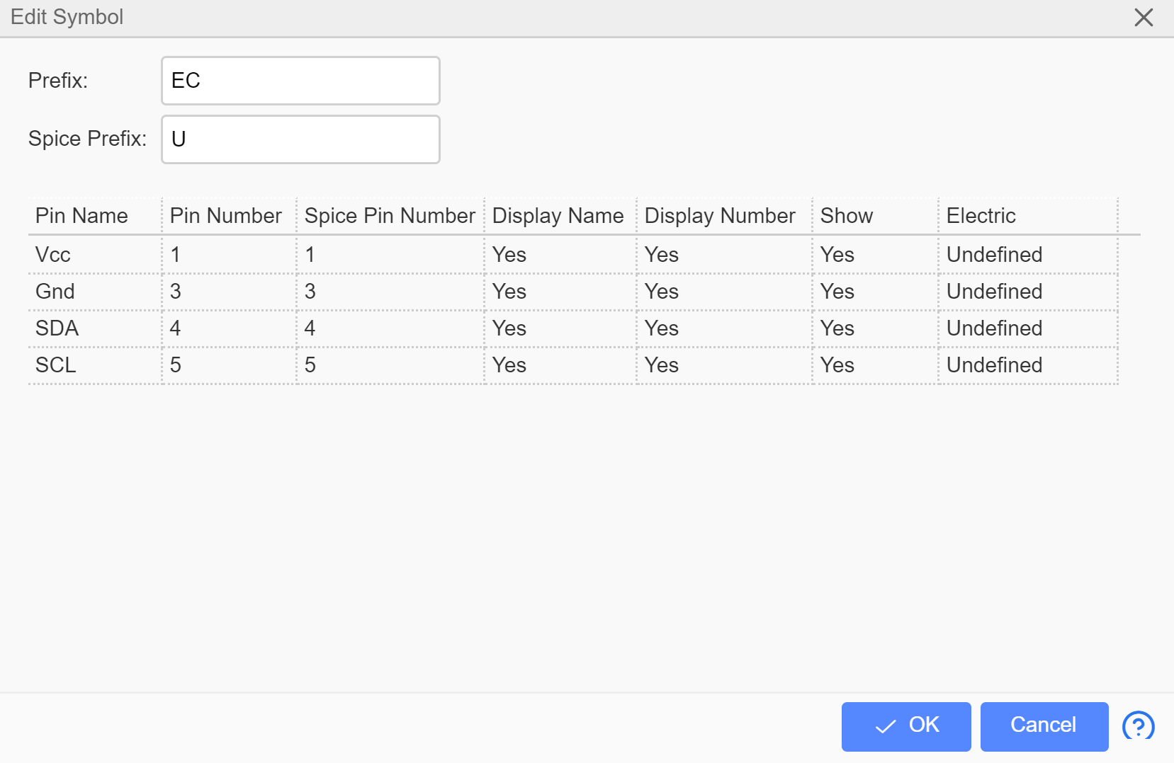
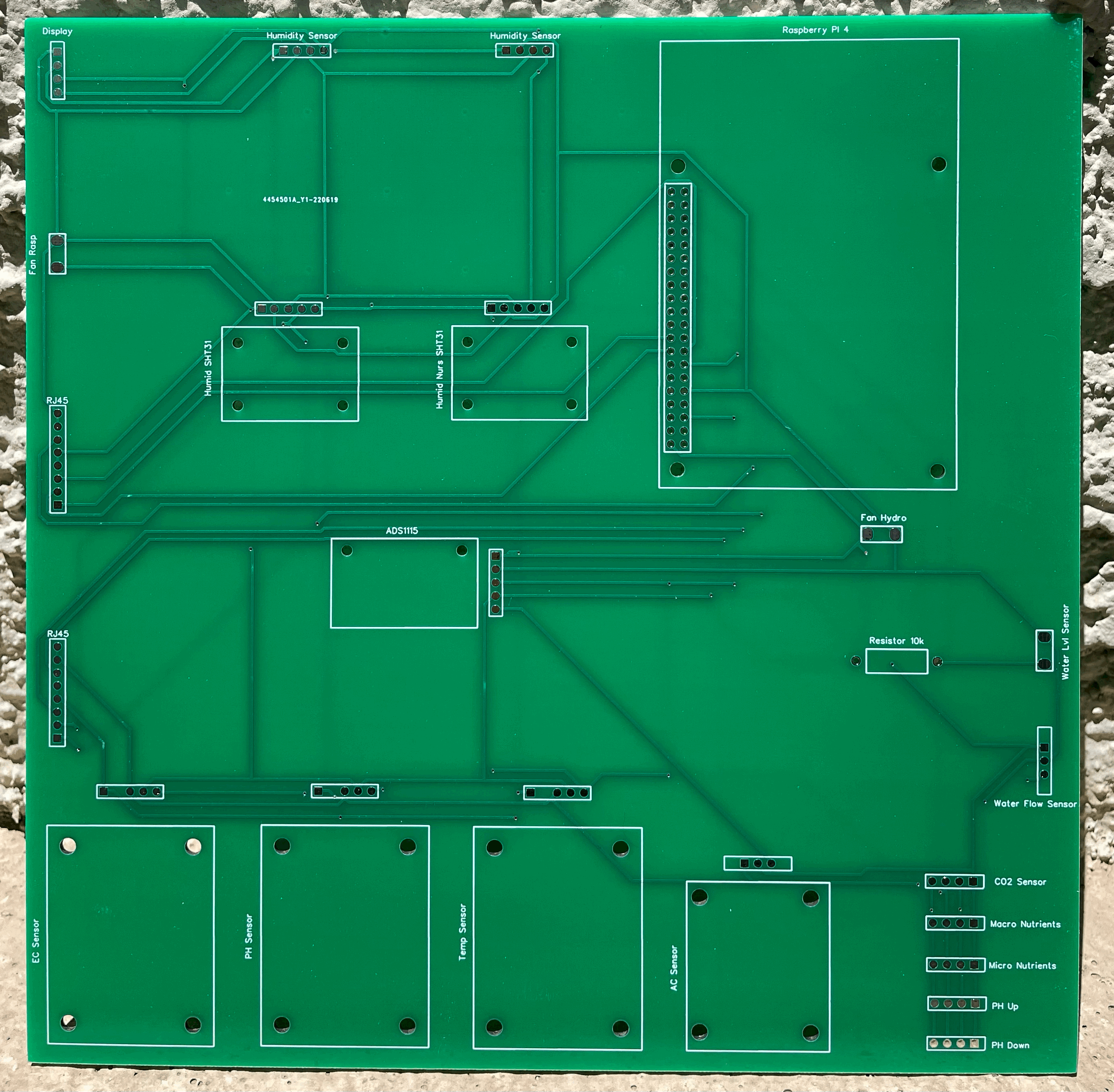
After you have replicated all the sensors into the schematic you need to tell the program how they connect. The Polygons you see below are called net ports and this determines how the sensors connect. For example, everything with VCC (5V Power) will be connected at the next step when you convert the schematic to the PCB. This is done to keep the drawing cleaner and because most PCBs will have multiple layers and the schematic is only 2D.
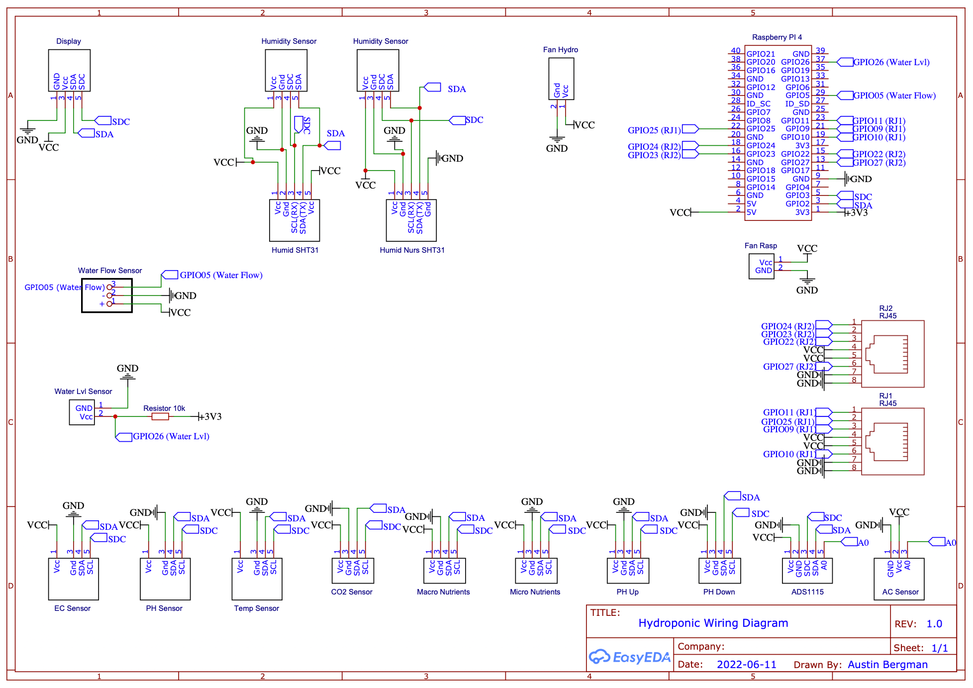
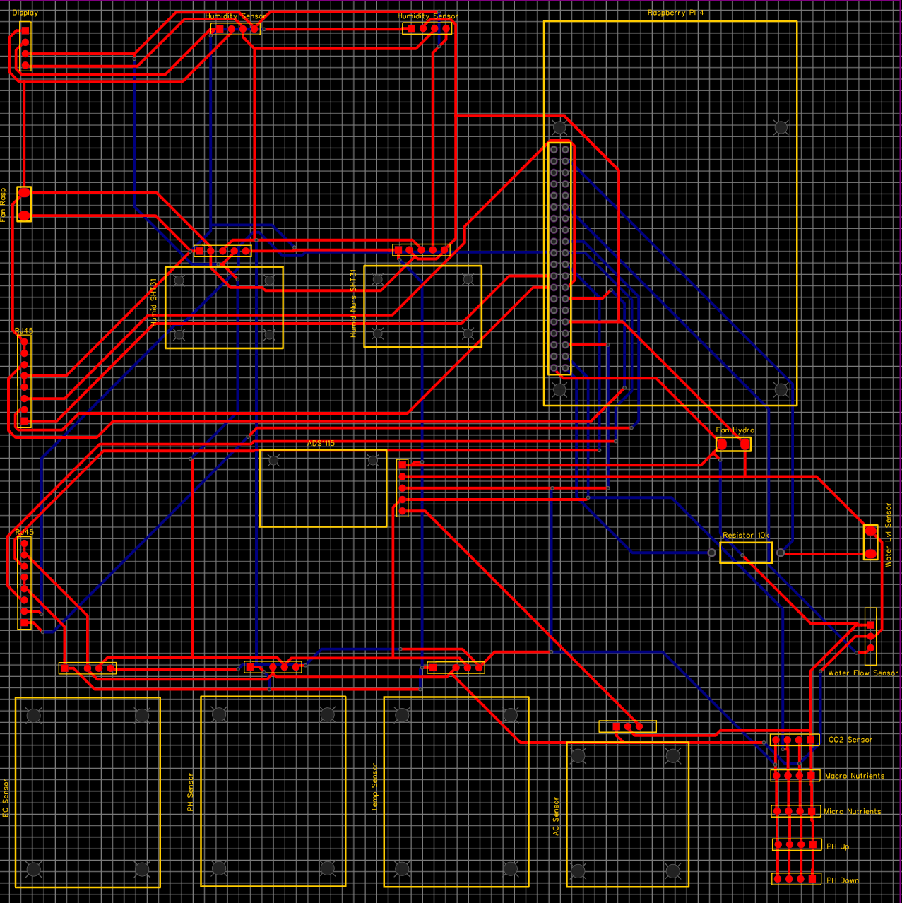
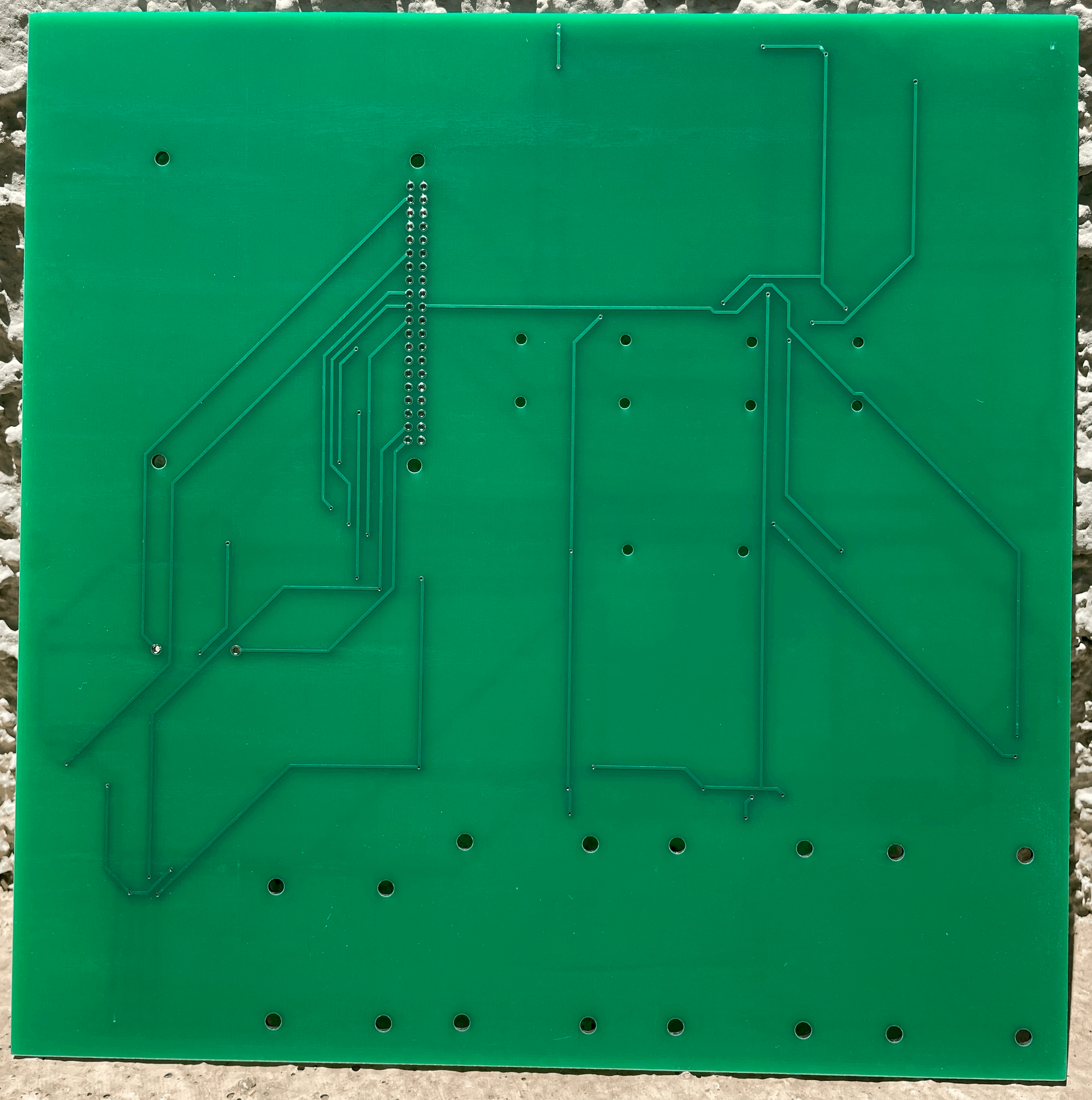
The program now know the sensors, their pinouts and footprints, and how each sensor is connected with each other. The last step is to convert this schematic to a PCB drawing. First you select the size of your PCB board, thickness of your traces (wires), and the number of layers. Then you place each part where you would like it to be on the board. Finally the program will connect all the sensors together using the net ports you assigned each sensor
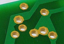
My roommate / brother is a machinist at a tool and die shop and the original idea was to convert this design to CAD so he could machine a copper plated PCB as seen below
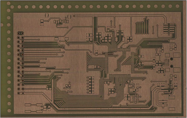
This was this plan as I believed a prototype PCB would be cost prohibitive. However after converting the schematic to the PCB a pop up came up in the program saying a PCB manufacturing could print me 5 of these for under $30 and get them to me within a week. I immediately clicked purchase and a week later a had fully functional PCB boards in my mailbox
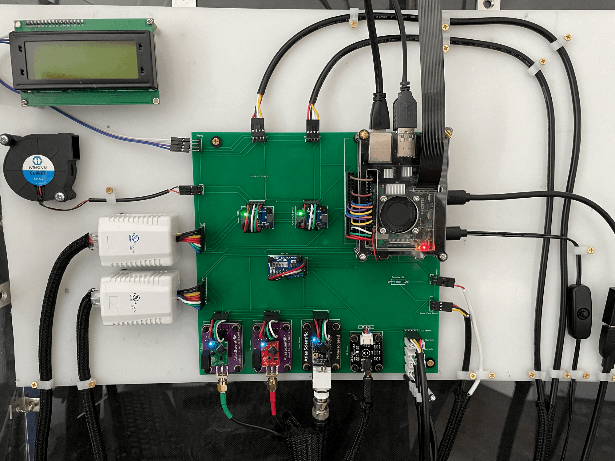
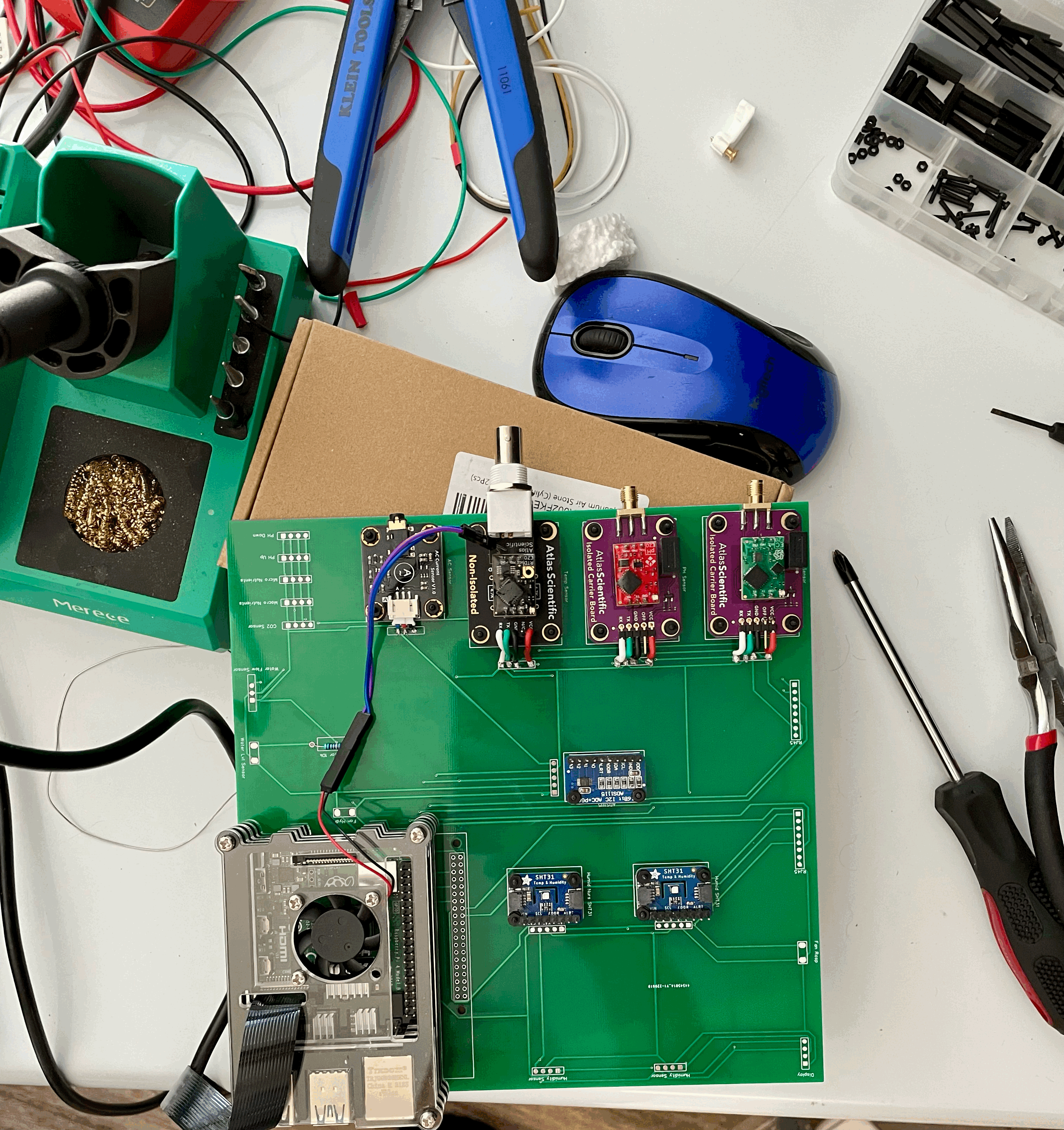
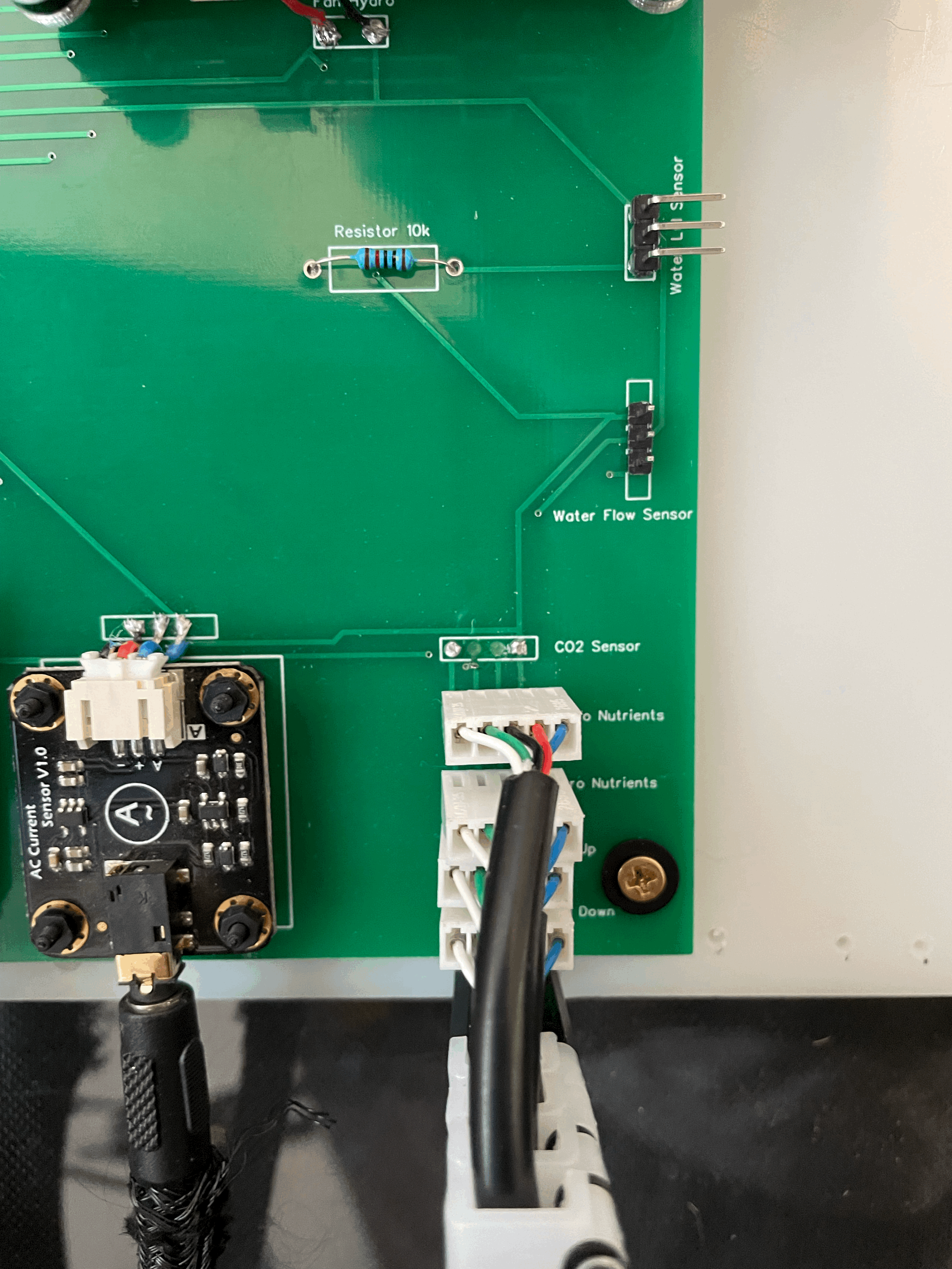
Now all I needed to do was get out the soldering iron and start migrating everything from the jumper cable setup
Notes: This is my first PCB I've designed and ultimately I'm just ecstatic that it worked, but if I were to redo this there are two things I would change
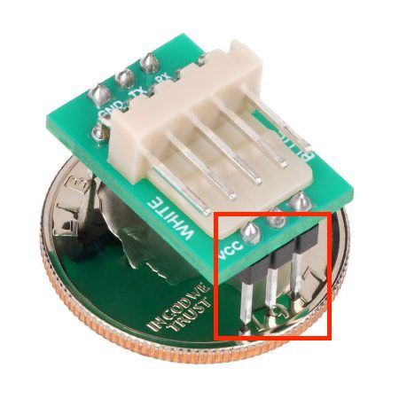
1) Nearly all the connections on the PCB are pads instead of through holes.
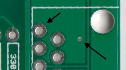
I had finished soldering everything to the board and was almost done connecting all the sensors when one of the pads ripped off. Luckily I had extra boards but I had to start over. Through-holes probably would have prevented this.
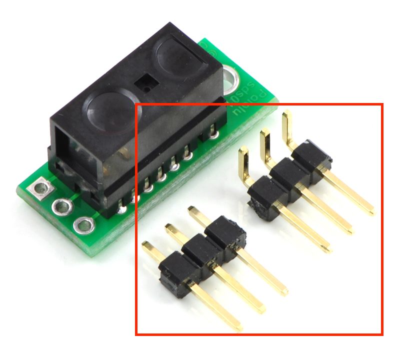
2) Most of the sensors are designed with through-holes like the image below
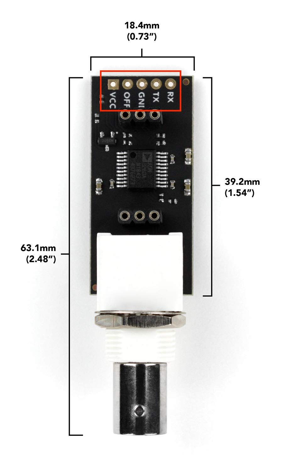
You can then integrate these sensor for either a jumper cable or PCB connection
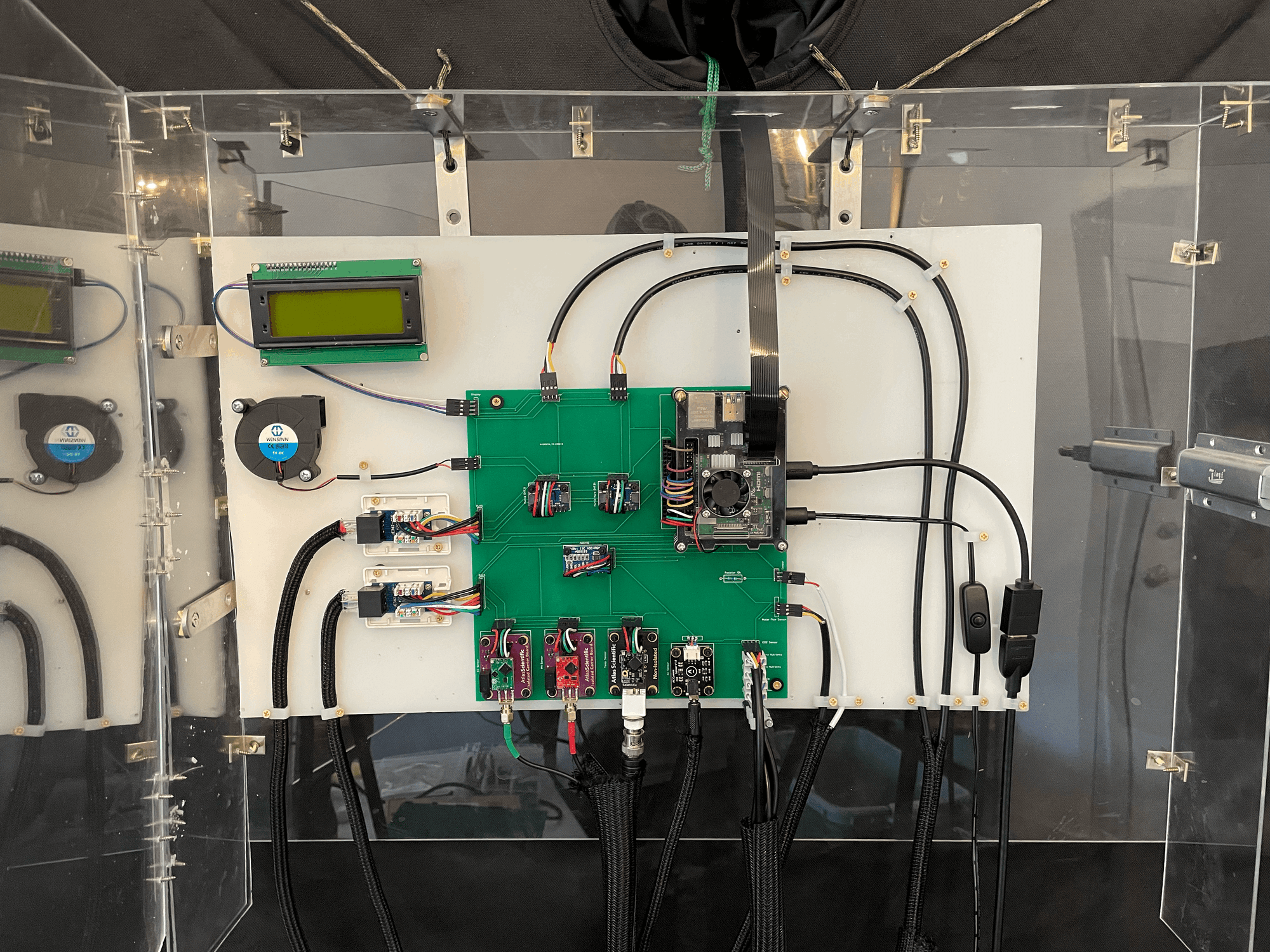
When I originally designed the hydroponic system I was planning on sticking with the jumper cable setup so I soldered all my sensors with the jumper cable connection. I didn't want to have to unsolder and re-solder all of my sensors so I stuck with the jumper connection. A second reason I stuck with the jumper cable connection was it gave me some flexibility if I incorrectly labeled one of the net ports. I, a little surprisingly, ended up labeling everything correctly but had that not been the case I could just connect the jumper cable to the nearest correct pad. Now that I have some more confidence and experience I would switch the pads on the PCB board to through-holes and the jumper connections on the sensors to PCB connections to eliminate the jumper wires all together. This would reduce the amount of time to connect everything and eliminate a possible failure point